Your Cart is Empty
Apparent Contours – Digital Algorithms for the Movement of Articulated Surfaces
Editor's Note: Michele Calvano recently published the book “Architettura delle Superfici Piegate” (in English: "Architecture of Folded Surfaces") about his research on some of the issues that affect contemporary architecture, such as the tessellation of complex surfaces. This is an exerpt from the still unpublished 2nd edition of his book. To read more about Michele and his work, check out our interview with him.

Apparent Contours – Digital Algorithms for the Movement of Articulated Surfaces
Articulated surfaces are defined as the category of surfaces that arise in the plane and that, when folded properly, build patterns formed by faces that are all equal or equal in groups. Thinking of replacing the hinges to the folds, we introduce movement into the system, resulting in joints that allow the new entity to assume different configurations in space.
Ordinary procedures of tessellation of complex surfaces start from the form designed to reach a tessellation, more or less dense with flat elements all different from each other. The manufacturing process of these surfaces, even if technologically and technically very accurate, does not differ much from a more handmade process, and the great mass of elements, all different from each other, leads inevitably to very expensive economic options. The original aspect proposed by the articulated surfaces is to draw a regular tessellation in the plane creating four faces or three sides which, turning on the hinges of contact, are articulated in the space creating complex forms of the changeable profile.
The overall configuration is determined by the movement of individual faces (or tiles) around the fold; the latter is no more than a portion of a straight line around which operations of rotation of the faces connected to it occour. This operation finds a simple resolution under conditions of stasis, but we have to imagine that the points belonging to the hinge do not have fixed coordinates but vary during the movement of the joints, hence the need to explore some themes of digital representation, to be able to solve the different conditions creatively.
1. Mathematical inspirations
Software of digital representation, and primarily that of mathematical representation, proposes the possibility of solving problems of geometric nature directly within the simulated 3D space. Prof. R. Migliari explains how today we can solve directly relevant geometry problems (e.g. the problem of Apollonius) related to the relationships between solid primitives in the space (n). He demonstrates how digital representation is able to apply the principles of projective geometry, surpassing the representation on the plane to resolve issues related to the forms in space.
The two methods, the mathematical and the numerical representation, can express (if deeply investigated) the added values that go beyond the mere direct representation of forms in space. This can only happen if we understand the substantive aspect of the new methods by acknowledging the nature of the information derived from these.

Fig. 01: “Extrinsic” coordinate of a point. The extrinsic coordinates are the coordinates x, y, z of point A with respect to the absolute reference system of the digital space.
For example:
We represent a curve of the first degree with CAD software (l1 Fig.01); we all know that the straight line drawn is defined as geometric place, in which the coordinates of the points satisfy clear mathematical rules. We note, in fact, that in the Cartesian plane, each point consists of two coordinates (x, y); a straight line can be written in implicit form as the set of points whose coordinates (x, y) satisfy the following linear equation:
ax + by + c = 0
We place a point at the centre of the drawn line l1, its position is related to the coordinates x1 and y1, which identify the point A1 in the XY coordinate plane. We apply a T shift to the line and to the point by making an l2 copy of the first and an A2 copy of the second. The new point is still at the centre of the line, but it will take on a new pair of coordinates x2 and y2 (l2 in Fig.01). We realize that the coordinates do not establish any relationship between the curve and the point; moreover, they do not indicate exclusively a variation of position determined by the T transformation of any point in the Cartesian plane. The point A, although belonging to the l curve, determines with it an “extrinsic” relationship, exclusively linked to the position compared to the origin O of the tri-orthogonal triad.
Most CAD systems represent curves through polynomial expressions of variable degree and parameters; the points on the straight line drawn in Fig. 02 are expressed through the following Bezier function:
P(t) = (1 – t)P0 + tP1, t ∈ [0,1] (n)
The function written presents a single t variable, internal to the domain of existence of the line. With t = 0, the point Pt coincides with the initial point P0; with t = 1, the point coincides with the final point P1. By applying again a shift to the line and to the point at issue, we note that the t variable, being equal to the value 0.7, will identify a specific point of the line (Fig. 02). In this way the point establishes an “intrinsic” relationship with the curve.

Fig.02: “Intrinsic” coordinate of a point. Intrinsic coordinates means the numerical value of the parameter t that identifies the location of the point on the curve or the parameters u and v, which identify the position of the point on a surface.
The t variable is a value associated with the given path, which in the case of the curve is a one-dimensional path, therefore, at a single variable; if we had as an entity of support a surface, the path would be guided by two intrinsic variables (composition of the movement in u and v). The knowledge of these parametric spaces intrinsic to the mentioned entities solves the problems inherent to the hinges of the articulated surfaces, in whatever position they may be compared to the tri-orthogonal triad.
2. Points, lines, surfaces

Fig. 03: Above – Flat development of the base module where EO and FO are the folds of the mountain. Below – Schematic representation of the movement of the form in which we highlight the geometries that guarantee the validity of the movement.
Let’s observe the module in the figure composed of “mountain folds” and “valley folds” which reduce it to two types of triangular faces. Now, let’s consider a simple first movement, turning the big triangles symmetrically around a hinge that passes through the point O and parallel to the Y axis of the global triad. In relation to the directions of the folds, the smaller triangles will rotate around the hinge OA, movable in space. At this point, even if in an anomalous condition, we encounter a classic problem of descriptive geometry, namely the capsizing of a plane around a line, the valley hinge (OA in Fig. 03). The resolution must therefore be sought in the path that the point E performs during its movement around the hinge OA; the path that occurs within a plane perpendicular to the hinge and which intersects the plane at issue in the line of maximum slope passing through E. By projecting the point in K on the hinge, we identify the line involved, the radius of the circle of capsizing, which represents the path of point E around OA. The projected point K is identified through three extrinsic coordinates (x, y, z) and an intrinsic coordinate (t); recalling the notions specified earlier, we realize that the parameter t will enable us to locate the projection of the vertices opposite to all the valley hinges of the small triangles (K1, K2… Kn), hinges whose position will vary in relation to the rotation of the big triangles. A plane is made to pass through all points on the hinges Kn, in which we draw a circle with a radius equal to EK, projection distance. In Fig. 03, we note that the circles appear two by two; the intersection between the symmetrical circles is the point that satisfies the condition of the same distance between the two hinges, respectively, the point E and F in the space. For each pair of circles, the intersections are two (the point E and the point G in the figure), but only one will generate the mountain fold. It is therefore necessary to proceed to the design of a selection algorithm with which to identify the correct solution. The extrinsic system would propose the comparison between the z-coordinates of the intersection points, but since the whole form is a system in motion, the solution would be invalidated under certain conditions.

Fig. 04:Selection algorithm of the intersection point between the circular trajectories able to generate the mountain fold. 1) circular trajectories; 2) identification of the showed circles; 3) intersection between curves; 4) parametric coordinates u and v, the point of origin of the tangent plane; 5) construction of the building plane, a new system for calculating the coordinates of the points; 6) evaluation of the coordinates with respect to the new reference system; 7) and 8) choice of the intersection point that meets the mountain fold; 9) construction of the triangular face, starting from the free edge and the found point.
Then we construct a new reference system whose coordinate plane XY will belong to one of the big faces of the module (Fig. 04). In the example, it belongs to the ABO face at heights, proposing the Z-axis of the new system parallel to the normal N of the face. The coordinate plane so placed, of infinite dimensions, divides the space into an upper portion of the plane (positive) and lower portion of it (negative). The boundary between positive and negative space will vary in relation to the movement of the triangular face, identifying a condition always true even when switching the spatial position of the module. Compared to the new tri-orthogonal system, we will evaluate the variable z of the two points of intersection of the circles in the space, selecting the one with the positive value. The four free hinges, extruded towards the selected intersection points, will ensure the dimension and the correctness of the movement of the module’s faces.
In the example presented it is clear that the movement in the different conditions is possible only by releasing the resolving definition from the extrinsic conditions to the module, while the result will be better as far as we will be able to tie the algorithm to its intrinsic qualities. Furthermore, the control of the form is entirely related to the accuracy of the geometrical conditions available to the system: by maintaining the length of the zipper unchanged, and the path of the point with respect to it, we guarantee the consistency of the moved surface. The rigidity of the forms is then simulated through geometric relationships that propose a resolving approach, exact and applicable to surfaces that are limited, due to the accurate computational description which requires its implementation. The reiteration of the procedure makes it possible to verify the relations of the movement of each part by tying it to the movement of the other. It is evident, however, that the large mass of data that this procedure offers makes difficult not only the control of the overall definition, but also the analysis of the different configurations that the surface can take on by obeying to different supporting geometries. Hence the need to take a further step in the research that proposes algorithms with which to efficiently manage a greater amount of data, while also taking in consideration the physical domain.
3. Forces and tensions
A new aspect of the work considers the possibility to simulate forces and tensions to help ensure the movement and the rigidity of the faces. The resolution of the system in motion is given to the synthesis of the problem into two main themes: the identification of the rigidity of the materials (the continuity between the parties) and the system of forces and constraints applied.
Let’s consider again the model of fold previously described, showing the new resolving approach. In this case the movement of the form is the result of special applied forces, able to simulate, in the digital space, the real actions that would be performed for the movement of the physical prototype. The forces cannot be applied to the continuity of the form; computers are not able to calculate the surface's reactions to an infinite number of forces. The module chosen must be discretized in a regular mesh, for which the tiles perfectly reflect the faces generated by the folds (Fig. 05).

Fig. 05: Above – Value of vertices and sides which define the relationships between the parts of the numerical synthesis mesh of the articulated surface. Below – Model of forces and constraints that characterize and contextualize the folded surface and move it accurately.
The surface, subjected to the right stresses, reacts by moving the faces that must remain of equal dimension and tied with each other, always following the same geometric constraints during the movement. For this reason, from the generated mesh, we must determine the topology by reducing the form to a rod system (Fig. 05): the triangular (or in other cases quadrilateral) mesh of the faces. In the physical domain, the reduction to a numerical model almost always allows us to deal with physical simulations. In fact, the mesh is able to describe in simple terms into its numeric lists (thanks to the value of the vertices and sides of the faces) aspects of topological represented structures.
On this geometric scheme it is possible to identify a system of forces enumerable and applicable to chosen lists of vertices, in order to obtain the correct movement of the parts. In the chosen model, we decide to implement the couples of small triangles bringing them closer. Having informed the system of the consistency, the nodes and the hinges of the surface, then we will obtain the movement of the joints. We analyze the chosen faces by identifying the vertices that define the fold (1 and 2) and the free vertices to approach (3 and 4). The first two vertices will define the axis of torsion, while the other two vertices will define the points of application of the forces useful for the formation of the torque (F1 red in Fig. 05). Obviously, the forces are applied punctually by creating a discrete system of actions on all pairs of small faces.
The cinematic mechanism that is created by operating on the vertices of the smaller faces is distributed over the entire model that moves in a disorderly way. The organization of the movement is due to simulation of constraints, which will give a direction to the folding of the surface. Let’s imagine to simulate the carriages placed at the vertices that will give the ability to slide along the direction d. Now, the removal of small faces tends to bring, in an orderly manner, the folded surface in the plane; this represents a boundary condition that determines the annulment of the information of mountain and valley folds. To ensure the possibility of return to the starting condition to the model, we add the action F2 (Fig. 05) to be applied to the pair of big faces; an action that tends to bring the big folds to the starting condition, in order to preserve the property of being valley. The system of actions and reactions leads to a fluid and controlled motion, showing a minimal amount of elastic deformation during the movement, which is reabsorbed immediately at the end of the cinematic action.
4. Conclusion

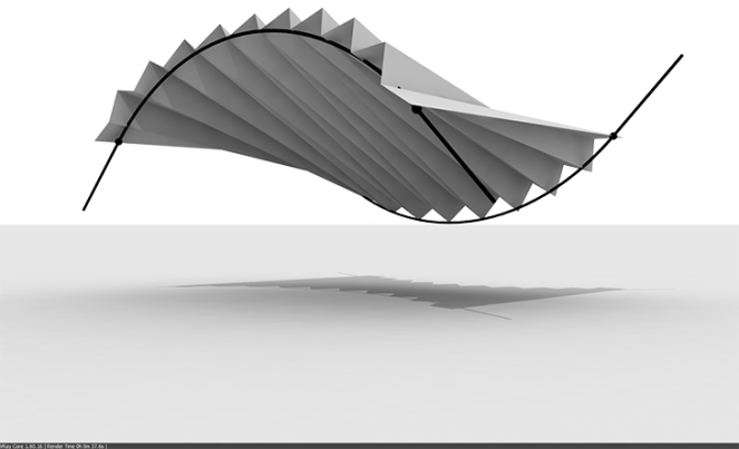
Fig. 06: Tessellation and movement of a pattern that from flat gets modified by going to recline on a surface with double curvature. Transformation that expresses the value of the research.
Let’s observe a more complex model of articulated surface, the Miura pattern, generally characterized by quadrilateral flat faces that allow this model only the deployment of the plane (Fig. 06). The original introduction of the neutral fold in the pattern allows the model, now divided into identical triangles, to change form in the space by reclining on double-curved surfaces. In this case, in addition to determining the mesh of linear elements, we have to introduce the forces acting on the angles at the base of mountain and valley folds. In regards to the neutral fold, the movements applied on it must have enough intensity to be able to maintain the angle flat, if not stressed in different directions.
An important condition set up in the system is the obligation of the articulated surface to slide on a mathematical surface of support, initially flat. In a second time, the NURBS surface is deformed by moving the two opposite vertices along the Z; the articulated model follows the mathematical surface that from flat becomes parabolic. The neutral fold allows the torsion of the surface regularly tessellated and folded, which does not change the individual areas of the faces during movement.
In this way, we are able to control the changing geometries that can be prefigured and tessellated through a structured mesh that, assuming different configurations in space, proposes apparent contours always changeable.
Michele Calvano's work is still mostly available in Italian, get in touch while he prepares the English version by visiting his blog and YouTube channel and by following him on Twitter.
To get a copy of Rhino click here.
Related articles

Also in NOVEDGE Blog